Tuesday, 10 June 2014

VOLTAGE SOURCE INVERTER (VSI) USING PWM SIGNAL GENERATED BY MICROCONTROLLER FOR THREE-PHASE INDUCTION MOTOR CONTROL

VSI in this project is using rectification and Inverter to convert dc-to-ac voltage. 3 phase gate IGBT is controlled by 3 phase HPWM techniques generated by Microcontroller. The speed of motor can be adjusted by pressing button at microcontroller part. By using PWM technique, the current used is efficiently reduced which means less power is consumed to run the motor compared to the system without PWM.


Methodology

Firstly, the circuit diagram is drawn using ISIS Proteus software as shown in figure above which include microcontroller PIC18F4431, speed control button, LCD display and optocouplers.


For the coding part, Picbasic Pro compiler is used to generate three-phase PWM signal. This compiler is assisted by MicroCode Studio for the compiling of the coding.   

After the coding is compiled, transfer it into microcontroller in ISIS Proteus software to generate the PWM signal. The signal is observed using digital oscilloscope inside the software. The finalized coding is then transferred into real microcontroller using PicKit2 software.
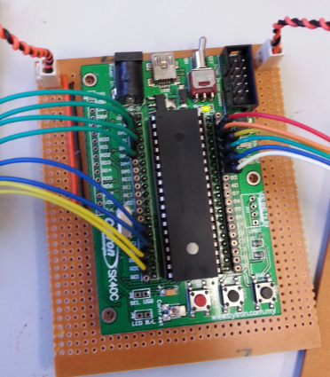

Hardware
The real project circuit is divided into four part, microcontroller, LCD, optocouplers and gate driver connected as shown in figures.

Microcontroller of PIC18F4431 is used to generate three-phase PWM signal. The PIC18F4431 is mounted on the SK40C and supply with 5V. The upper part jumper is connected to the optocoupler circuit whereas the lower part jumper connects to the LCD screen.


IR2130 is used as the gate driver to turn IGBT on and off and supplied by 15V. The input of driver from pin 2 until pin 7 is connected to the output of the optocoupler and the output of driver is then connected to the input of IGBT circuit.

Three set of IGBT are used as inverter that converts DC voltages into AC voltages. The input comes from gate driver circuit and the three-phase output is connected to the motor.  


Result


Figure at below shows the high side PWM output from the gate driver. A maximum voltage of about 25V and minimum voltage of 14V is recorded. The mean voltage of 11V is provided for three-phase high PWM signal.


High side PWM output (gate driver)

 high side and low side PWM
High and low side PWM ( gate driver)

The output of PWM signal which the upper signal (yellow) is the high signal and lower signal (blue) is the low signal. The deadtime is created when the signal pass through the gate driver circuit. the deadtime is 22 -60 ns.

Single phase IGBT output voltage signal 

When the three-phase output of the IGBT is connected to the motor input, it successfully turns on the motor and the speed can be adjusted by pressing the increase or decrease button at microcontroller input part. Some voltages and current are measured during the motor is running.


PWM
Without PWM
Current
0.048
0.255

The table shows that by using PWM technique, the current used can be efficiently reduced which directly means less power is consumed. Whereas the system without PWM, more current is required to run the motor which means it is less efficient since more power is used. Hence, PWM technique is preferred compare to system without PWM.


Cooking oil filter - for Donut Maker

List of components:-
1.            Filtering assembly
2.            Fill hose
3.            Haight 8U ductile iron Gear pump
4.            Castors
5.            Stainless steel Filter tank
6.            Handler
7.            Pump stand
8.            ¾ inches Stainless steel pipe
9.            Cube melter
10.          Filter bag
11.          Heating element

We use the current product in market for our reference. We improve by directly move down from frying reservoir to oil filter reservoir, more easy. And add the heater, improve the flow rate of suction pump.


2.0     Concept design


1. Frying oil play an important role in quality of the fried food like doughnut.

2. The amount of oil absorbed by doughnut varies from 15-20% of their final weight.
3. There are many aspects that affect the quality of frying oil like:-
            A. oil properties and composition
            B. transport and, packing and storage of oil
            C. process of frying
            D. the evaluation of the frying oil during use


Based on the table above , the best choice is palm oil or palm oleic as it has average iodine value  , high oxidative  stability in high temperature , average melting point, average percentage in saturated, monosaturated fatty acid and low percentage  polyunsaturated fatty acid .


How Oil filtering work?

Filtration is a straightforward task. In frying doughnut, filtration with papers or woven  cloths can remove particle down to about 5micro meter in diameter for vegetable oil  a contaminants must be removed before enter the oil tank again. This will ensure the quality of doughnut and frying oil itself. Filter paper should be clean regularly, to discharge the foreign material removed from the oil after oil filtering process was carried out. If thus is not done the latter can form a bed of debris which continues to deteriorate will damage the oil pump.

Advantages of oil filter machine
-Improved food quality
-prolong the life if the oil and fat up to 80%
-Cut oil and fat cost by up to 40%
-filter the oil directly from cooking temperature
-safely and easily handling the oil
-reduce the needed for fryer cleaning

Parts in oil filtering system
1.    Barrier seal double pump w/relief valve
- Help pump the oil inside the tank
2.    3 set singaflex stainless steel flange hose
- help in transfer oil from oil tank for filter process and transfer back to oil tank
3.    Wooden block
-help in support the stainless steel pipe and absorb oil lost from pipe
4.    Oil reclamation
-          Store the unused  oil
5.    Steel pipe valve
-open path for oil to flow
6.    Filter paper
 –remove foreign material inside the oil
7.    Steel pipe valve
-          Open or close the path of oil flow
8.    Filter  oil tank
 –filter oil and store clean oil and let it cold down before enter the oil tank again

Feature of barrier seal pump
-Barrier fluid ring rotate through 360degree to meet various flushing arrangement
-Large nut end cap design allows for easy access for maintenance and adjustment of barrier fluid ring
-Sealed, lubricated radial bearing provides shaft stability and ensure proper alignment for the seals

Feature of singaflex stainless steel pipe
-Made from fines quality stainless steel pipe
- Safety factor4:1 ranging from 6mm to 550mm
-high working temperature of 200 degree to 700 degree Celsius


Flowchart of design method


Preliminary design

The preliminary design bridges the gap between the design concept and the detailed design phase. In this task, the overall system configuration is defined, and schematics, diagrams, and layouts of the project will provide early project configuration. During detailed design and optimization, the parameters of the part being created will change, but the preliminary design focuses on creating the general framework to build the project on.
After selected MS.LEE as project manager of all groups, we had been informed to build mini donut maker which have lower production than previous one. We need to change all parameter but the concept of design is still remains the same. We change all the configuration and consider how to build the machine and quickly improve our group project and come out a lot of new configuration.

Cooking Oil Filter
The device is designed to be used with Donut oil tank. It performs four functions:
·         It filters wasted oil for re-use.
·         It melts shortening.
·         It holds shortening.
·         It filters used shortening for re-use.
The major parts of design are gear pump, filter assembly, cube melter, filter tank, electrical board for switching the pump to generate on or off and heating element. Gear pump can able to pump hot cooking oil back to oil tank after process of filtering. Filter assembly contains of filter bag which can replaced by new one and easy to change it.

Cube melter is used to pre-melt some shortening in a pan on the stove and pour it into filter tank. Filter tank is where the dirt and shortening will stay at their when running the oil filter process.

Layouts and Configuration


The device is below the oil tank and able to receive hot cook oil after operating hours and pass through filter bag and melt cutter so that the dirt can been eliminated more effective and portable as shown above the layouts.


The concept design is suitables for this design because the greater size of concept design is more than enough for the design at here and getting more reliastic so that on detail design or fabrication will easy to understand and given the dimension to the component.


Lists of components:-


1.            Filtering assembly
2.            Fill hose
3.            Haight 8U ductile iron Gear pump
4.            Castors
5.            Aluminum Filter tank
6.            Handler

7.            Pump stand
8.            ¾ inches Stainless steel pipe
9.            Cube melter
10.          Filter bag

11.          Heating element

Measuring Tilt Angle with Gyro and Accelerometer

Background knowledge

         Basic understanding on how the Segway works is; when the IMU is tilting to a certain angle, the accelerometer give command to the stepper motor to tilt to the respective angle. The gyro sensor reacts by giving command to the motor to tilt the angle to the reference position.

          The main and most complicated issues of self-balancing Scooter are the sensors. The sensors are very important as they give us the inclination of the bar regarding the base and the speed of its angle change. For this kind of scooter, we need an accelerometer and a gyroscope. The combination of these two devices provides us of very precise results because the error of one is cancelled by the other and vice-versa. In short, we could say that the gyroscope tells the short-time reading and the accelerometer the long-time reading.


This is the latest circuit which has Stepper motor, Arduino Uno, motor driver L293N and IMU sensor in the bread board. Using complementary filter for combination of gyro sensor and accelerometer is programmed into Arduino Uno and Stepper motor also.

this program is using Complementary filter which is easy for beginner but recommended to use Kalman filter that much more better so that it can more precious. PID control is needed to control the output of stepper motor but I didnt include it into it because I am still working on it. Hope this will help you!

a. Do the initiation for Arduino.


b. Set up the formula for angle and initiate LCD screen to read the data.


c. Plan the angle for the sensor angle and the reaction of stepper motor.


Process Flow Chart


References
1. http://www.ele.uri.edu/courses/ele205/Arduino%20-%20Learning.pdf
2. http://arduinotutorials.blogspot.com/
3. http://www.instructables.com/id/Accelerometer-Car/
4. http://www.instructables.com/id/Use-an-Accelerometer-and-Gyroscope-with-Arduino/
5. http://retardokiddo.blogspot.com/2010/09/arduino-processing-adxl330.html
6. http://www.nuclearprojects.com/ins/info.shtml

[mini-project] Water Bottle Submarine

METHODOLOGY
The main body of the submarine is made by a 1.5 liter mineral water bottle. We cut a 2 small rectangular hole at the mineral water bottle to let water enter into the bottle when it is placed on water. There are two 500 ml mineral water bottle are connected to both bottom side of the main body of the submarine so that it is heavy enough to submerge into the water.
            Then, we put a balloon into the main body of the submarine. The balloon is connected to a bicycle through a plastic tube. The balloon function as a ballast tank and control the buoyancy force of the submarine. We pump air into the balloon to let the submarine float and remove air for the submarine to submerge. We also had cut a few small hole at the main body of the submarine to let the air in the balloon to escape to the surrounding when it is in the water and we want the submarine to float. This enable the submarine to float and submerge according to our will.

            In order to let the submarine to move left and right, we use two motor and a remote control. We stick a ruler to the submarine and place the two motor on both side of the submarine. We put all the electric circuit and battery  into a small plastic bag that can seal and open easily to prevent form water entering the electric circuit board and battery. When we want the submarine move right, operate the motor on left side and if move right, operate the motor on right side. If we want the submarine to move forward,  operate both the motor and if backward, operate both the motor in opposite direction.

Calculation of buoyancy force
When floating in water
Mass of submarine = 3kg
Weight of balloon= 3x9.81 = 29.43 N
Volume of balloon= π
                     = π
                                = 4.19x
Volume of submarine submerge in water = 0.75L = 0.00075
Buoyancy force=
                          = 1000(4.19x )(9.81) + 1000(0.00075)(9.81)
                          = 48.46 N
 > Weight of balloon
Net force acting on submarine = Buoyancy force- Weight of balloon
                                                  = 48.46N - 29.43N
                                                  = 19.03N